CRAFT
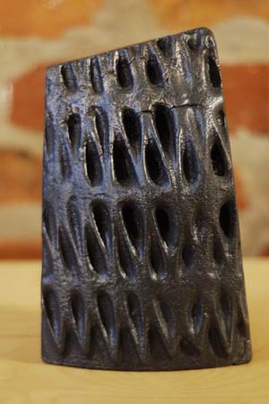
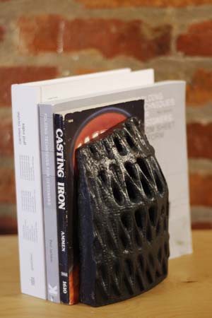
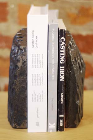
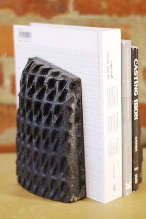
Iron Bookends
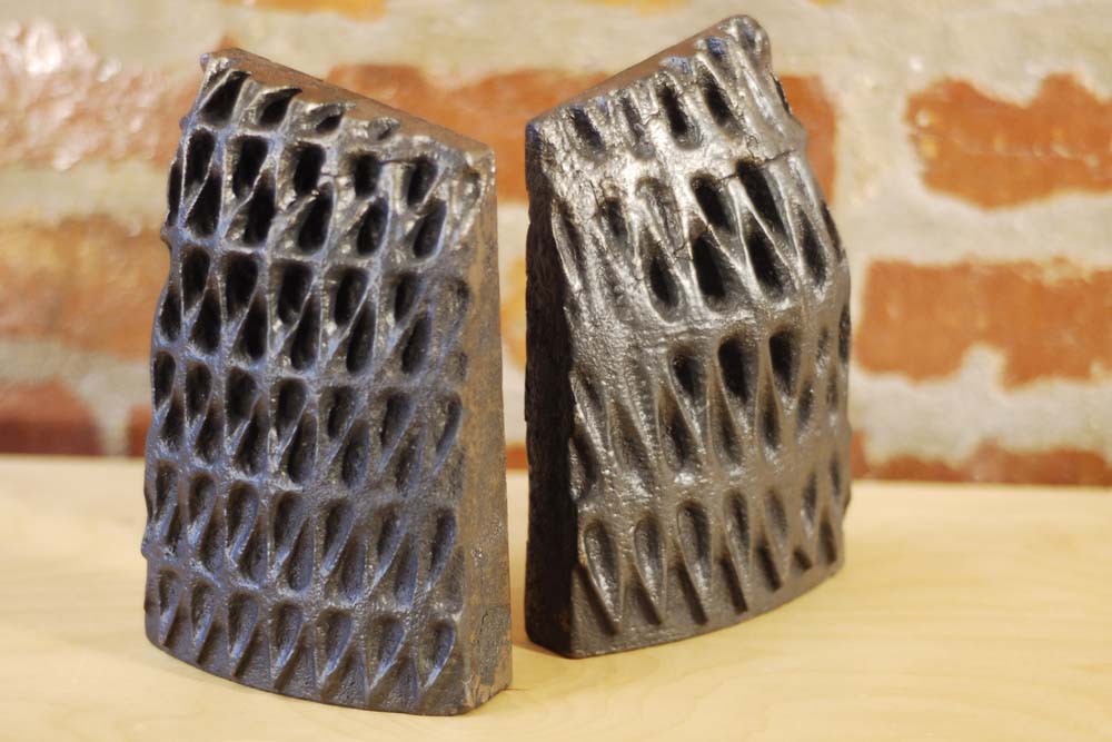
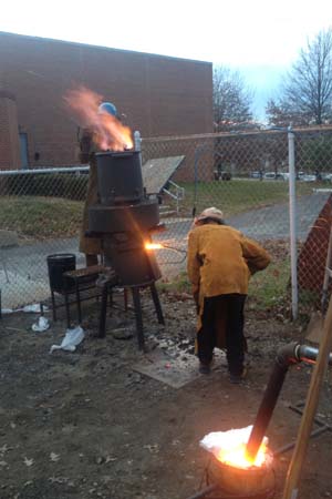
I made these cast iron bookends in December of 2012, mostly just to visit my friend Christian Benefiel in West VA and cast some iron out there with him and his students. They had just spent the semester building their own cupola for a competition held at Sloss as part of the National Conference on Cast Iron Arts in spring of 2013.
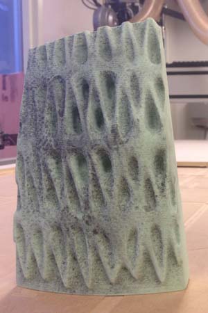
Personally I wanted an easy pattern because making a mold and casting iron is very time consuming. I had just downloaded a plug-in for grasshopper called Weaverbird and wanted to play around. Most of the logic in this is directly from the Wb tutorial.
.jpg)
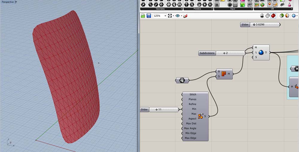
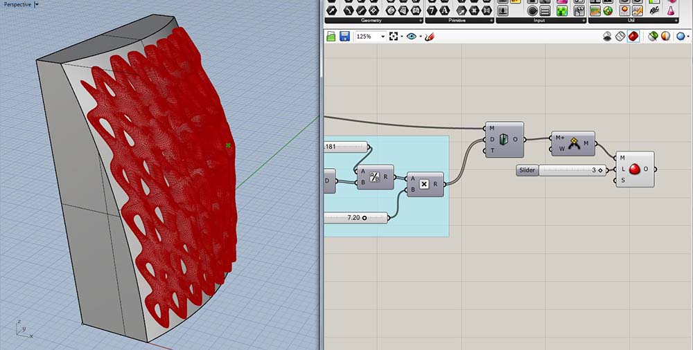
Above left is the Rhino view-port and above right is the Grasshopper canvas. I modeled the general shape and size that I would like to have for the bookends. Now I will modify that geometry with Grasshopper to add a texture and make the bookends a little more interesting. The red surface is what will be used as input.
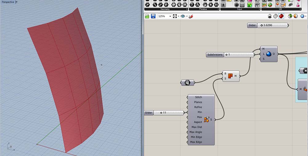
This part is just making a mesh from my NURBS surface. I'm dividing it with a minimum of 11 (actually 12) mesh planes.
Now divide each mesh plane into 8 triangular planes using Weaverbird's Loop Subdivision tool.
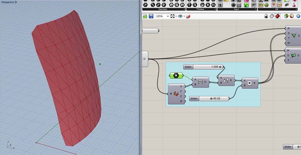
Next is an attractor point. This finds the inverse distance from each vertice to the "attractor point", then multiplies it by a constant which will be used in the next slide to create some new mesh planes.
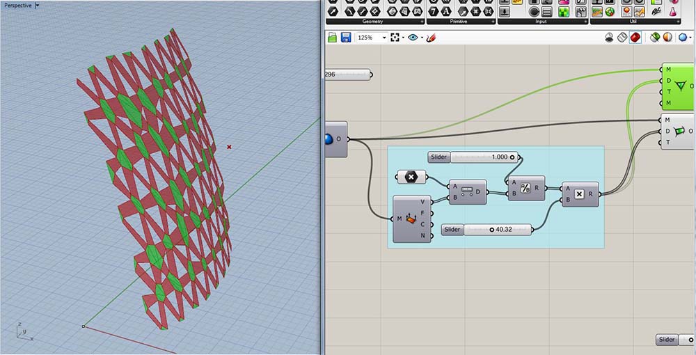
Two new mesh objects are created. Thanks to Weaverbird, they only require vertices and an offset distance (which came from the attractor point.)
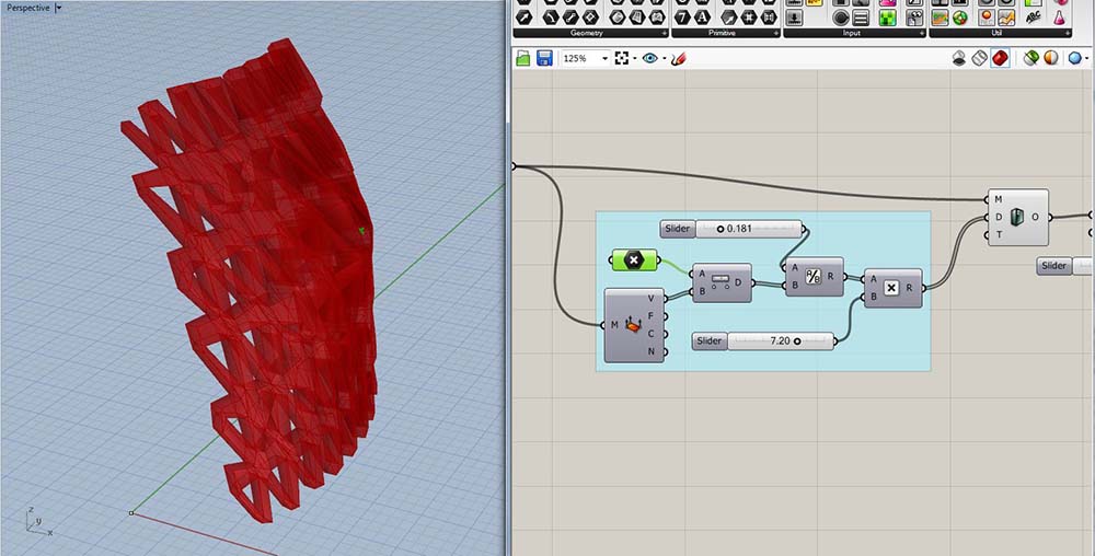
Now, using another attractor point for distance, and the Wb Thicken component a solid is created after the meshes are all joined together.
All that's left now is to join the new meshes and use Wb's Catmull-Clark Subdivision to smooth the mesh edges.
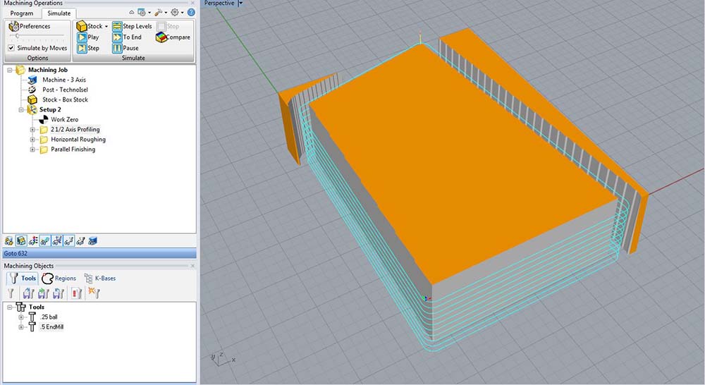
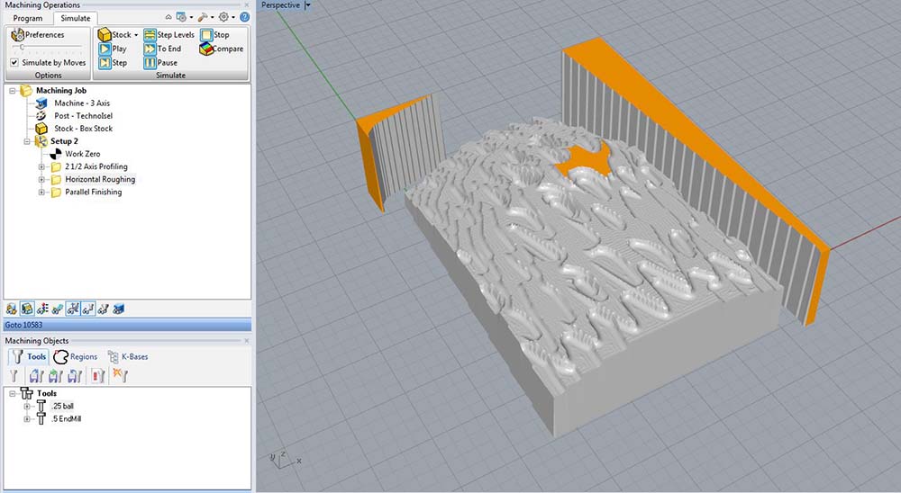
This is the RhinoCAM interface. My first step here is to cut the perimeter of this shape.
In the next step, we rough out the part removing the bulk of the waste material. This is typically done by stepping the bit down and removing everything possible, then stepping down more and removing everything possible resulting in a topographic approximation of your part.
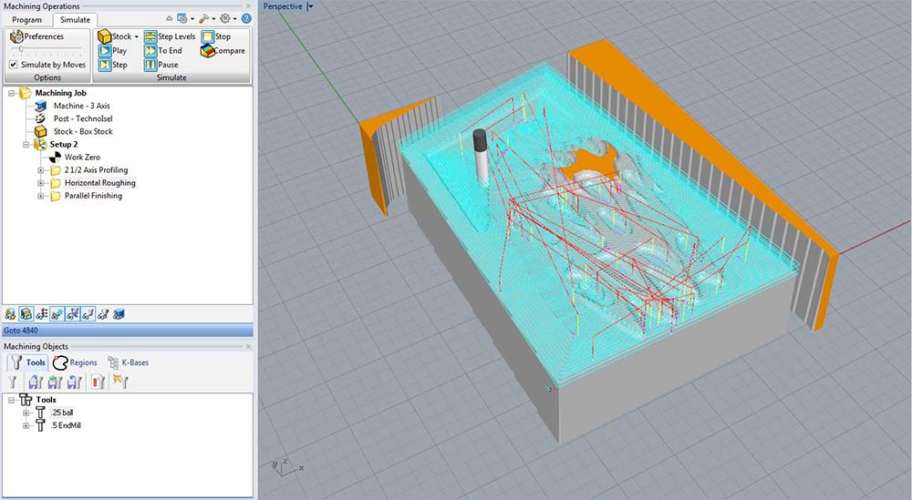
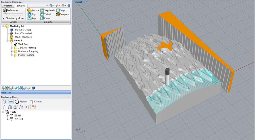
Here you can see the simulation a little bit further along. I also showed the tool-paths. The cyan lines are the centerline where the bit is engaged in material. Red are rapid moves when the tool is not engaged.
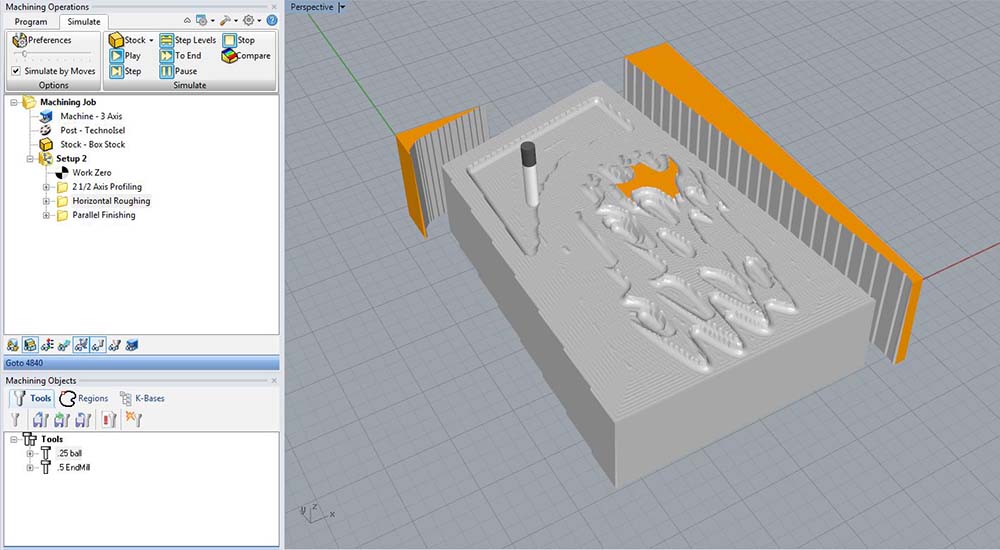
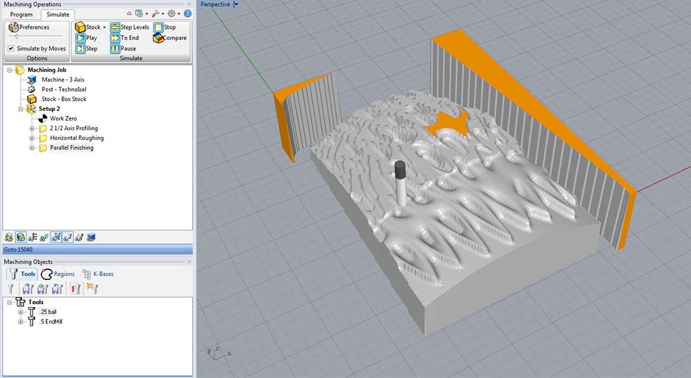
This is the finished roughing pass.
Now for a parallel finishing pass. I did one vertical and one horizontal to see the different effects it has in these tight spaces.
The roughing pass leaves just enough material for the finish pass to take a little off and leave a smooth finish.
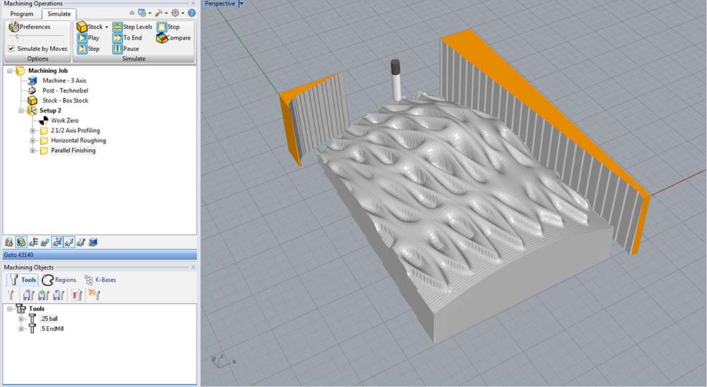
Here is the finished simulation.