CRAFT

back to my work

Chair - Spring 2013

Walnut and Ash


Chairs

I started this project on June 5th from a sketch. The chair to the left was designed and prototyped over the period of one week. I spent four days designing, one day cutting the seat, connector and back and another day building the legs and putting on one coat of finish. This is by no means a complete project, it will likely go through a few more iterations before I do a production run of 4-10 chairs. I will be designing a table to go with the chairs within the next month.


- Ryan (6-14-13)

3d Print | Design 2 | Chair Seat | Chair Back | Connector | Legs | Shop | Essentials | Dry Fit

Final Assembly | Trimming Legs | Sanding | Fininshing | Plastic Prints | Final Images

Design 1

Chairs At about 8:30pm on June, 5 2013 I decided to sketch in a little hidden park I had seen a day or two earlier on a morning jog. I didn’t really have any objective, but I had just been discussing with a client who was interested in having some furniture made for their dining area. I made this sketch and got excited about it.
Chairs I’ve already produced a number of versions and prototyped a snap together chair last year, which was really good for figuring out the angles, heights and dimensions. More photos of that process can be found here.
Chairs Because I had designed that snap together chair in Rhino (a 3d CAD program), it was relatively easy to pull a number of the measurements directly from a previous file. In this image the grey lines are from the old file. I decided it would be a good idea to keep the stripped down version as a template for the future, and that named my file (Chair_Template… I know its super original.)
Chairs Alright, so here is what my template file looks like. Some of these screenshots were taken retroactively to fill in the gaps in this explanation on process
Chairs One of the first things I did was draw the backrest contour lines onto the plane that defines the surface that would touch the eventual sitter’s back. The next step was to draw the centerlines of the legs.  Lines are great for getting the structure together.
Chairs These lines have two control points (one at each end) so I can change the angle in the x and y direction by moving the endpoints and I can move the line. In this way it’s pretty easy to get a good idea of how you want the legs to look, its sort-of like an armature in that it’s the structure that you will build your 3d shape from. I also massed up the seat and back. The two surfaces that cut the back are also pulled from my last project. I figured them out by carving then reverse engineering the carved surface with a couple of rulers.
Chairs
Ok, so here’s where it starts to get fun. Instead of just picking a line, drawing two circles and lofting between them I imported the line geometry into Grasshopper (a plugin for Rhino which allows for a visual programing interface). This allows me to set up some rules that will draw the final solid geometry from a set of inputs. In this case there are 5 inputs, two lines for the centerlines of the legs, a point and a line that define a mirror plane and two sliders, one for the top diameter and one for the bottom diameter.
Chairs
Now I can move the entire line or end points around and see what the leg would look like in real time without re-drawing.
Chairs
I can also change the diameter at the top and bottom. I’m not going to make circular legs, but it gives me a quick way to visualize how I want this thing to look.
Chairs
Here’s the output from Grasshopper. I’m feeling like I’d like to do a little drawing by hand.
Chairs Once I arrive at an initial set of angles for the legs, it’s easy to output plan, side and front elevation and perspective contours and print them.
Chairs I like to draw in pencil when I need to work quickly through a bunch of ideas.
Chairs Trace is great!
Chairs I’ll go back and forth between the computer and paper for a while until I’m confident with the way it looks.
Chairs I’m starting to like the way this connector between the seat and back looks
Chairs Just want to get a few more ideas out there; I’m worried about the connector putting a ton of stress made from solid wood so I want to try a couple more ideas.

3d Print - zCorp 310plus

Powder Based Rapid Prototyping

Chairs I want to see this thing in real life, so I’m going to send it to our 3d printer. This is a shot of z-print, it takes an *.stl file and slices it up into a bunch of layers.
Chairs

This is one of our 3d printing machines. It’s a powder based system and it uses a liquid binder to join the powder together in the areas you want to remain solid.

The white rectangle through the window is divided in half with the left side being the “feed” and the right side as “build.” Essentially it’s an HP printer (it actually uses an HP print head) that pushes over a new layer of material from the feed side to the build side, prints the binder in the area you want solid, then feeds another layer of material over.

The size of each layer in the machine is the size of the slices in your model so in this way we can quickly print any solid or “watertight” object that is modeled on the computer.

Chairs This is what it looks like when it’s finished printing, pretty much the same as when you started.
Chairs Chairs I like to start to excavate the print with a paint brush,slowly working around the delicate print.
Chairs Here the feed side is lowered and I’m moving printer material over from the build side back to the feed side.
Chairs As the feed side fills up you want to get the air out by ramming this card into the tray
Chairs Chairs Chairs
Chairs

I can still glue it back together. It broke when I picked it up out of the powder.

It would have printed fine in plastic, but this is a good indication that I have more work to do on the design to make the connector stronger, that piece needs to be bomber.

I forgot to take a photo but the last bit of cleanup is done in a box with a vacuum creating negative pressure while you spray the model with a little air gun to clean out the little hard to reach areas.

Chairs Chairs Chairs
Chairs Chairs

To the left is a second iteration, inorder to keep it from breaking, I connected the back support to the seat and made the footrest a little thicker. This printed fine, I was also a little more careful pulling the print.

The black on the back is from ink in the print head that was not purged. The old print head was part of the problem with breaking too. I’m not too worried about the color so i didn’t bother to waste material purging the rest of the ink out.

Design 2

Chairs

I decided that I really don’t like the way the back looks so I sketched another version.

Below i'm transfering the drawing into Rhino.

Chairs Chairs
Chairs Here’s what it looks like with the backrest completed.
Chairs

Now it’s time to take another look at these legs. I used grasshopper to get the initial sketch together, now I want to make them square so I can fabricate them with a mortise and tenon.

In order for this to work they will need to be planar. It helps to move the construction plane to the location of the legs to make that happen.

Chairs Here’s how the legs look after being extruded.
Chairs This is another 3d print of the model at this point. It’s close to complete, I like the lines but it needs some pieces connecting the two front legs and the two back legs.
Chairs
I really like to use Grasshopper for simple tasks such as figuring size and location of these two crosspieces. When you can just move a slider back and forth to see every option it’s very easy to see what’s in your head.


Chairs
This definition takes the centerline of for each of the legs (the back legs in this case) as input along with the elevation (how high cross piece will be), thickness and height (how wide and tall the cross piece will be in section). I draw a point between the two endpoints of each input line. From those two new points, which are controlled by the elevation slider, I make a new line that connects the input lines. Then I extrude that connecting line in two directions (thickness and height). Now I can slide the sliders around until I’m satisfied with the location and size.


Chairs Here are all the iterations I’ve gone through so far.
Chairs And this is what I‘m going to build

Creating the Seat

Chairs I copy the chair over and create bounding boxes around each part that will be cut on the CNC router. This gives me a rough idea of the material I’ll have to glue up.
Chairs

The first part I’m going to mill out on the CNC is the seat. It’s curved on the front and back, so this means I’ll have to mill both sides.

Step one is to create a bounding box. This is a six sided solid that contains the extents of your part. The actual stock should be larger, typically I add 1/4 inch to all sides and 1/8 to the overall thickness.

Chairs

Here I’ve offset the bounding box by 1/4 on all sides. I drew in a waterline at the center elevation of the part as well to help me find the depth for the contour cut (the cut around the perimeter of the part to release it from the waste stock.

The yellow line is the face border of the top surface. That has been projected up above the part to the top plane of the stock.It will be used to contain the tool paths that cut the surface and as a contour line to cut the part free from its stock.

You can't see them, but I have also made 4 points which will be used to create holes to line up the part once it's flipped.


Chairs

This is the roughing pass. The red horizontal lines are rapid moves where the router bit is not cutting material, the yellow lines are plunge or retract moves and the cyan lines are where the tool is engaged in material.

You can see that they are all inside the yellow containment line. It's important that this is above the surface or it will not work as containment. I always put it on the plane of the top of the stock.


Just the toolpaths here

Chairs

Here is a preview of the roughing pass.

To write these toolpaths i'm using a piece of software developed by MecSoft called RhinoCAM. It's essentially a VisualMill plugin for Rhino that allows you to edit your model as you program the toolpaths. As you can imagine it's ridiculously convenient to be able to make changes to your model while you're writing toolpaths.


Just the preview here

Chairs

RhinoCAM, or any piece of CAM software for that matter, allows you to specify a tool, spindle speed, feed rate, step down, step over, drive geometry, containment geometry, and many more parameters. Once these have been set it will allow you to preview the outcome of your settings and verify that what you want to happen will actually happen.

Then you can export your file as 'g-code' using a post processor that knows how your CNC machine wants it's info.


Preview and toolpaths here

Chairs

This is the finish pass.  I’ve left an 1/8 of an inch in the rough pass for the finish pass to remove.

Depending on what you want to know, you can preview only the stock, the stock with toolpaths (above) or just the tool paths (up three photos)

Chairs

This is the drilling pass, which actually moved to the first operation when I ran the file. Once the operations (toolpaths) are made, they will be carried out by the machine in the order shown in the browser on the left hand side of this image. It's possible to re-arrange them at any time.

Also shown is how the tool will cut the contour around the perimeter of the part.

Chairs This is the bottom after it’s been flipped. It’s not a fancy process, I’m just going to drive screws into the pilot holes which are symmetrical to the stock perimeter. When I flipped the part in Rhino I made sure to do so along the midpoint of the stock not the part.
Chairs Preview of the finish pass
Chairs

This is the CNC router cutting my ash panel.

I forgot to take photos of gluing up this panel, but I show it later for the back piece.

The dust collector is hooked up to the hose at the top of the screen. You can see the chips moving up toward the collector (it’s collecting most of them even though it doesn’t look that way).

Chairs

Here you can see the router bit in the upper right hand corner.

It’s a ball end bit, meaning it has a round tip. This is better for cutting out surfaces because it has the least deviation in tool paths that have z travel such as my surface.

If we were cutting a planar pocket (removing the inside of a mortise for instance) a flat end bit would be preferable.

Chairs This is the finish pass. It started on the left and moves right.
Chairs Here’s another shot of the finish pass
Chairs Chairs

Here’s the contour cut. I did this on both sides to make cutting the final contour of the seat a little easier.

You can see the screws I used to hold down the part, they are also to align the part when I flip it.

Chairs

Rough pass on the back side

Chairs

You can see the mortise for the connector in the part at this point

Chairs

Rough pass finished

Chairs

Finish pass

Chairs

You can see the tool holders on the left hand side, they are the little black things on the rail. The machine is programmed to know these locations and can change between four different tools in the middle of the cut.

On this cut I used three tools, a 1/8 inch drill, a 1/4 inch flat end compression bit and a 1/2 inch ball end bit.

The actual router (called a spindle) is almost hidden by the dust collection hose, but it has a round silver cooling fan attached to it.

The blue knobs on the front of the table are valves that open the vacuum table.

Chairs Chairs Chairs
Chairs Chairs I cut the excess off with a bandsaw

Creating the Back

Chairs

This is the roughing pass on the front of the back. Once you have your tools and toolpaths programmed in, and you know you'll be using the same settings, it's pretty easy to just re-use all the settings and change the part geometry.

Chairs

RhinoCAM allows for the user to store tool libraries and Knowledge Bases. Knowledge Bases are pretty cool, they allow the user to store a set of operations and re-use them later on for another file. It makes things go very fast.

Chairs

Contour of back. This was also a flip mill process, but the images are really similar to the seat so I didn't include them here.

Chairs Chairs

This is the wood I’ll use for the back, it’s rough sawn 8/4 ash

The first step is ripping them into the rough size on the table saw, they are now laying on the jointer ready to be planed

Chairs

That’s a thickness-planer on the right, the jointer is on the left with the board on it. A thickness planer will make the boards an even thickness, the jointer can be used to make one face flat, then it goes in to the planer to get the opposite side, then back to the jointer for the third side, then the table saw, then back to the jointer.

A jointer can take out twist, cup, warp or bow. A planer just makes the board a constant thickness with respect to the reference face.

Chairs Chairs

These are boards which have been planed on 3 sides, next they’ll be cut on table saw to make both edges parallel, then back to the jointer for the final pass.

Now we’re ready to glue up

Chairs

First it’s always important to get cleaned up and get your clamps out, when things get complicated you really want to take a moment to figure things out ahead of time. This one is pretty easy though.

Chairs

I like to put a bead of glue on all the faces that will be laminated together first

Chairs

Then smear it around nice and even

Chairs

I was really tight on material for this panel, the edges had to be really close to square, when that’s the case it’s important to put a clamp in the middle first with almost no pressure on it

Chairs

Then put the other two on around it and slowly tighten them all together, this way you are able to move the boards back and forth and get them as square as possible.  You know you have the right amount of glue when little beads pop out of the seams when it’s clamped

Chairs

Then set it off to the side and out of the way.

Chairs

This is the panel we just glued up on the cnc

Chairs

After the roughing pass is done the grain lines will show the contours that are cut into the part

Chairs

Here the perimeter has been cut

Chairs

flip the part

Chairs

Then rough out the back

Chairs

Another shot of the roughing

Chairs

And here the second contour has been cut I forgot the pocket for the connector piece on this one, didn’t realize it until later on, so I have to cut that by hand.

Chairs

Here are the back and seat with the board I’ll use for the connector

Making the Connector

Chairs

It’s going to be this L shape, I’m not sure that the mortise and tenon will be quite strong enough, it’s kind of a ton of pressure for any connection and I have to lose a ton of side grain to side grain contact in order to completely hide the tenon inside the connection.

Chairs

But, why not give it a shot! Here are the dimensions

Chairs Chairs


This is the board cut to the lengths

I use a clipboard constantly. Here are my stinky sketches with dimensions for the tenon.

Chairs

Ok, steps on how to cut a tenon. First get your blade height

Chairs

make sure that your blade is square

Chairs

Make sure your jig is square

Chairs

In both directions

Chairs

Line up your mark with the jig

Chairs

This is a shot of my tenoning jig

Chairs

Here are the first two cuts

Chairs Chairs


This is how it looks after all four shoulders have been cut, this is not the best for strength because you’re losing surface area on your side grain to side grain contact between the two pieces.


Chairs Chairs

Next is cutting off the shoulders.  You really want to make sure that blade is exactly at the correct height

Below is how the tenon comes off the table saw. It's important to work with sharp tools. To the right below is the tenon all cleaned up.


Chairs Chairs

Chairs

Chairs

I mark the top and bottom of the mortise from the tenon, then mark the sides with the marking gauge which is still set from laying out the tenon.

Then use the mortising machine to cut them out.

Chairs

Chairs

You can see the layout lines, the chisel will make the hole square and the auger bit (inside the chisel) removes material to make way for the chisel to push down.

Once it’s set this goes pretty quick

Chairs Chairs

Chairs

Chairs

I always make my tenon a little big when I’m doing only a few connections, it reduces setup time and I like using a chisel.

Fit’s pretty tight at the mouth, but I went a little wide on the inside. It’s not as pretty as it looks.

Always put glue on the mortise, not the tenon! If you have a tight fit it won’t go together.

Usually there’s not really a need to clamp a mortise and tenon if it goes together square, this connection is a little sloppy

Chairs

Chairs Chairs Chairs
Chairs

Here’s the CAM file for the CNC in rhino.

Chairs Chairs Chairs
Chairs

I set up the vacuum table to suck directly to the part. The black gasket seals the perimeter and the red plugs close holes on the table that I won’t be using. The vacuum will suck through the open holes inside the black gasket and hold down the part.

Once things are set, there is an incredible holding power. It’s enough that I can’t move the part pushing on it with all my strength.

It took about 2 min to cut. With all of these processes, setup is the huge time sucker. If you're making many parts of the same part it's pretty efficent.


Chairs
Chairs

Next I trim off the stock with a bandsaw and flush trim the rough edge left from the bandsaw with a router table.

If I were going to production on this I'd use a sacrifice sheet and cut all the way through on the CNC router to save time.

Inorder to do this you need to use a spoil board or sacrifice sheet. The vacuum table will suck through MDF and hold down a part, that would go between my stock and the table above left.

Chairs

Fabricating the Legs

Chairs

Now for the legs

Chairs

I pulled off all the dimensions

Chairs Chairs Chairs
Chairs

It saves an incredible amount of time to get all your dimensions together and compose a good shop document. There is nothing worse than running back and forth between your shop and computer, or setting up your laptop in the dusty shop.

I started out with a 4/4 rough sawn piece of walnut, the same wood as the connector piece,cut that down to the lengths I need, ripped it to the widths, then they’ll be planed and joined it all square like before

To the right is an angled tenon, very similar to the straight tenon earlier but you start with a miter, and cleaning up the shoulders is a little trickier.

Chairs
Chairs

I’m getting ready to lay out the mortises. I'll chop them out first, then taper the legs.

Chairs

To taper the legs I just lay out the lines, then cut along then on the bandsaw and join off the rough edge left from the bandsaw

Chairs

Now the mortises are cut, the legs are tapered and we’re ready to lay out the cross pieces

Chairs

Next are the cross pieces to keep the legs from splaying out. They are compound angles and taper in both directions. It’s way easier to cut the tenon at an angle then try and angle the mortise

Chairs

These mortises have been cut now and it’s all ready for a dry fit.

I always assemble without glue first to make sure everything is working.

Clamps help you pull things square. Never use a hammer!

Chairs

Shop Photos

Chairs
Chairs
Chairs
Chairs

Essential Tools

Chairs

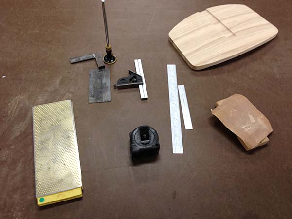
I consider these tools to be essential.

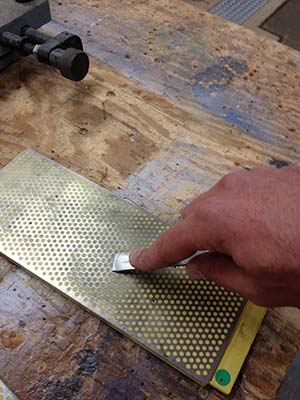
A good sharpening block is well worth the good money you'll pay for one. This saves you time and you will actually sharpen your tools which will allow you to actually make good work.

A card scraper or cabinet scraper is the most usefull tool. A good one is about $10-15, it can be used to clean out glue from inside corners, but once you learn how to sharpen it the cabinet scraper becomes much faster than sanding and leaves a much cleaner finish.

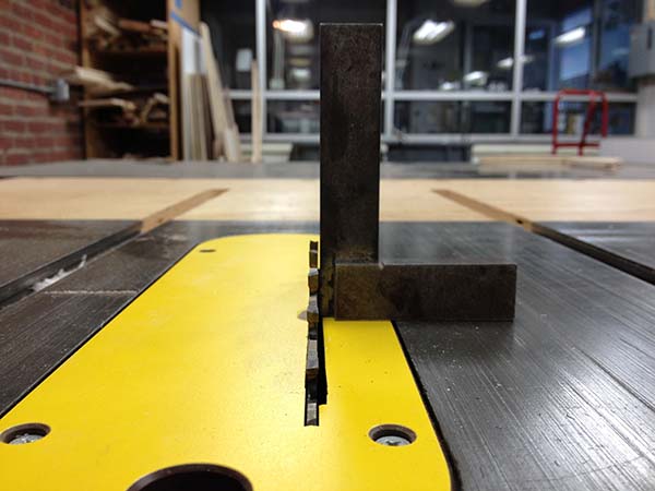
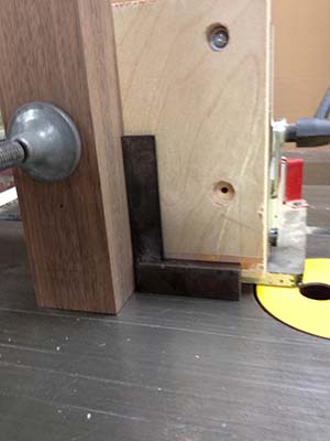
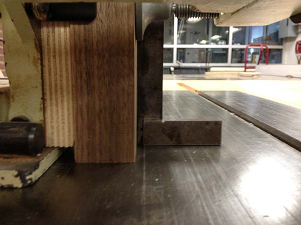
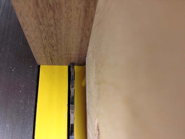
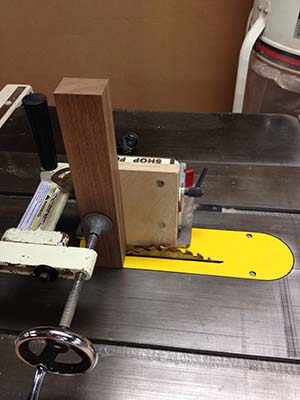
Machine square and combination square are necessary to make your tools square, you can't eyeball this or use the marks on machines.

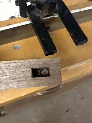
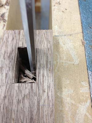
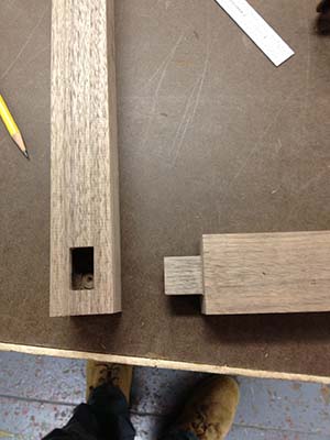
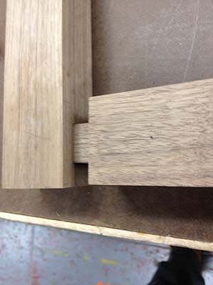
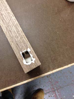
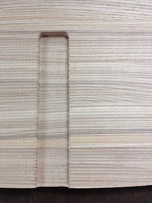
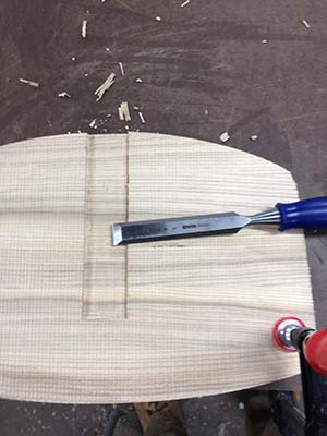
A marking guage is essential if you want to make tenons and mortises. you can get by without one, but you won't be making many joints very fast.

I am a sucker for 6 inch rulers, I probably own 5 of them, and I'll always buy another one if it's cool. General makes one that has decimal to fraction conversions on the back! The 12 inch ruler is super usefull too, but not essential.

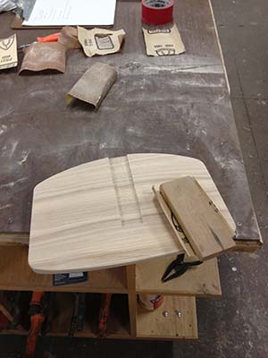
A sanding block should always be used with sand paper. It's faster.

Chairs Here are the legs with the seat on top Chairs
Chairs

Dry Fit

Chairs Chairs Chairs

Final Assembly

When your shoulders don't quite line up perfectly there's a pretty sweet fix.

I cut a little too far when removing the excess at the shoulder.

I cut the strip on the table saw. Don't worry too much about getting a little glue on the work, you'll clean that off with a sharp chisel in a minute anyhow.

I should have included the Marples flush trim saw as an essential tool too. It's like $12 at Home Depot, I bring that with me everywhere I go.

Chairs Chairs
Chairs Chairs Chairs
Chairs

Chairs

This is how the shop document turns out. Tons of notes and scribbles. The page on the right are my notes for next time I build this thing

Chairs

To the left is the clamp up for the connector to the seat. It's the same as the back.

To the right are the completed legs after they have been rough sanded.

I do a shaping sand down to 100 or 120 before the first coat of finish.

If I apply polyurethane, I thin that down 2:1 with mineral spirits for the first coat, with oil I just apply the first coat full strength. I consider both of these finishes to be a sealer coat and will do my finish sanding after that coat, usually up to 220 grit.

Chairs

Trimming the Legs

Chairs

Although I had the angles in CAD for the bottom of the legs, it would have been useless to cut them ahead of time because of the unpredictable nature of wood.

Set the chair on a flat surface and cut a block to mark from.

Then just freehand saw it. Trust yourself, it'll be fine. The trick is to score along two lines perpendicular to the face using your fingernail as a guide.

Once both lines are scored (I usually leave the line and go slightly below, in this case to the right)change the angle of the saw to follow both lines and go slow, only cutting on the draw stroke.

Chairs

Sanding

Chairs Chairs Chairs
Chairs

Here it is complete from 8 sides.

I screwed the legs to the seat with two pocket hole screws, one in each side. This will be plenty to hold the seat in place and it will allow for expansion of the seat over the seasons.

Chairs
Chairs Chairs Chairs

Finishing

Chairs

I used Waterlox this time for the sealer coat, which is probaly all the further I'll take this iteration.

It needs some testing and abuse before I build another one, and I dislike finishing. It seems like a waste of time in this case.


Below are some plastic 3d prints. We had a power surge which fried a board in the printer just before I was going to print. I wanted the plastic ones because they are much more durable. It's also a good example file

Chairs

Plastic Prints - Fortus 250mc

Chairs Chairs Chairs
Chairs Chairs

This printer uses ABS plastic for the build material. The slighly whiter plastic you see is support material that is necessary to make the part and can be removed by soaking in a mild bath of sodium hydroxide and water.

To the left is the finished part. The printer is essentially a hot glue gun that extrudes a thin line of plastic. You can see the toolpaths pretty easily in the seat.

I can throw this model across the room with little fear of any damage.

Chairs Here's the lineup. All the iterations together.

Final Images

Chair

Chair

Chair